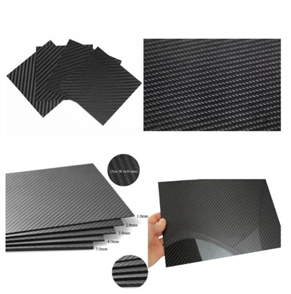
In the field of advanced materials science, carbon fiber tubing has become a benchmark material in engineering applications, organically combining extremely low density with excellent mechanical properties. From aerospace structures and high-performance automotive components to precision industrial robot systems, carbon fiber tubing is gradually replacing traditional metallic materials such as steel and aluminum due to its outstanding specific strength and specific stiffness. A deep understanding of its complex manufacturing processes and performance formation mechanisms is crucial for engineers and manufacturers committed to improving the efficiency of composite material applications.
What is the manufacturing process for carbon fiber tubes?
The manufacturing of carbon fiber tubes is a highly complex and multi-stage process, the core of which lies in transforming precursor fibers into high-strength, high-performance structures. Unlike isotropic metallic materials, carbon fiber tubes exhibit significant anisotropy, and their mechanical properties largely depend on the orientation and layup of the fibers. In industrial practice, the preparation of high-strength carbon fiber tubes mainly relies on three mature processes: pultrusion, filament winding, and fiber winding.
Pultrusion process
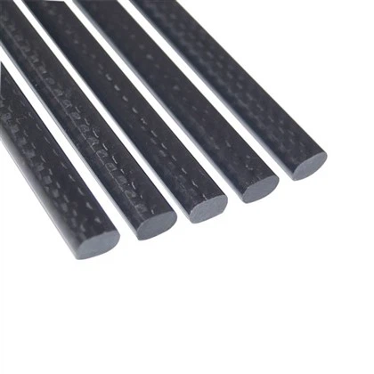
Pultrusion molding of carbon fiber tubes is a typical continuous manufacturing technology, mainly used to produce profiles with constant cross-sections. In this process, continuous carbon fiber bundles first pass through a resin impregnation system (usually epoxy resin or vinyl ester resin), and are then drawn into a heated mold for molding and curing. As the impregnated fibers pass through the mold, the heat triggers a cross-linking reaction in the resin, achieving curing and shaping of the material, ultimately forming a dense, solid structure.
This process boasts excellent production efficiency, making it particularly suitable for mass production scenarios. However, its process characteristics typically restrict fiber orientation to the axial direction (0° direction). While this can significantly improve axial stiffness and strength, it often requires reinforcement through additional structural design or multiaxial strengthening methods when subjected to torsional loads or multiaxial stresses.
Prepreg winding technology
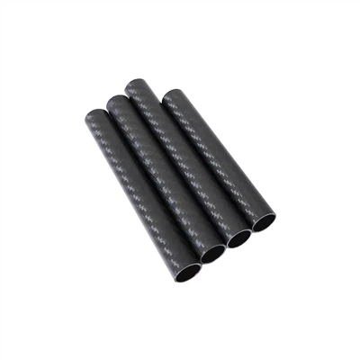
This process is widely regarded as the industry benchmark for manufacturing small-to-medium diameter, high-precision carbon fiber tubing. Its core lies in the use of prepreg-carbon fiber material pre-impregnated with resin in a specific ratio. During production, technicians wind multiple layers of prepreg onto the surface of a precision-machined steel or aluminum mandrel, according to design requirements.
The key advantage of this method lies in the high degree of controllability of the layup design, allowing for flexible setting of fiber orientation angles (e.g., 0°, ±45°, 90°) according to load requirements, thereby achieving customized optimization of structural performance. After winding, the component is typically wrapped with heat-shrinkable tape and cured in a controlled temperature environment (e.g., an oven). The tape provides uniform compaction during heating, which helps increase the fiber volume fraction and reduce porosity, thus significantly improving the overall mechanical properties and structural density of the product.
Fiber winding
For large-diameter carbon fiber tubes or those requiring high pressure resistance, fiber winding is one of the most engineering-adaptable manufacturing technologies. In this process, resin-impregnated continuous fibers are uniformly introduced and laid on the surface of a rotating mandrel. Through precise control of the carriage movement trajectory by a CNC system, the fibers can be automatically laid with high consistency according to preset geometric paths (such as circumferential, helical, or polar directions).
The core advantage of this process lies in its high degree of control over fiber orientation and distribution, enabling optimized design for internal pressure loads and complex multiaxial stress states. Therefore, fiber winding performs exceptionally well in structures such as pressure vessels and composite material pipelines that must withstand internal pressure or coupled loads, significantly improving the structure's load-bearing efficiency and safety margin.
Comparison of carbon fiber tube manufacturing methods
| Feature | Pultrusion | Roll-Wrapping | Filament Winding |
| Fiber Orientation | Primarily longitudinal (0°) | Multi-directional (Customizable) | Helical and Hoop |
| Production Speed | High (Continuous) | Moderate (Batch) | Moderate to High |
| Precision | Medium | Very High | High |
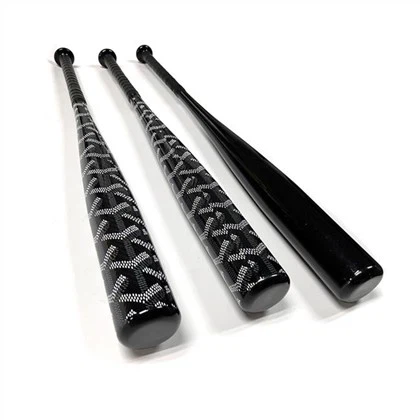
| Common Use | Construction, Tool Handles | Aerospace, Sports Gear | Pressure Vessels, Large Shafts |
| Cost Efficiency | Best for long runs | Best for high performance | Best for complex loads |
Why is fiber orientation so important in carbon fiber tubing design?
The mechanical properties of carbon fiber tubing depend to a large extent on the structural layout of its internal fibers, a factor that is often more decisive than the material's intrinsic properties. Because carbon fiber is inherently a uniaxial reinforcing material-providing maximum strength and stiffness only along the fiber axis-by rationally designing the "stacking sequence," it can achieve structural performance far exceeding that of metallic materials under specific operating conditions.
In typical high-performance carbon fiber tubing, engineers use different angles to balance different forces.
0° layup: arranged along the axial direction of the tubing, it mainly provides longitudinal stiffness (Young's modulus) and tensile strength to resist bending and axial tensile loads.90° layup (circumferential layer): Distributed along the circumference, it enhances the resistance to radial deformation, suppresses the "ellipticization" effect under compressive load, and improves the internal pressure bearing capacity.±45° layup: This layer bears shear and torsional loads and is a key layer for ensuring torsional stiffness and shear strength. The absence of this angle will significantly increase the risk of torsional failure.
The design of high-performance carbon fiber tubing is essentially a delicate trade-off between the proportions and sequences of the aforementioned different fiber orientations, which typically constitutes a company's core technological capability. For example, robotic arm structures rely heavily on a high proportion of 0° layups to enhance stiffness, while drive shaft components require ±45° layups to optimize torsional performance.
Studies have shown that even a slight deviation of the fiber orientation from the design angle (by only about 5°) can reduce overall structural performance by up to 15%, placing extremely high demands on layup precision during manufacturing. Therefore, both prepreg winding and fiber winding processes require strict angle control.
Furthermore, the symmetry of the layup structure is equally crucial. Asymmetrical layups are prone to generating residual thermal stress during curing and cooling, leading to component warping or twisting. To address this, specialized manufacturers typically use finite element analysis (FEA) to pre-simulate the layup design and curing process, predicting and optimizing stress distribution before actual production to ensure that the final product meets the stringent requirements for dimensional accuracy and structural stability in high-end applications such as aerospace.
How does the choice of resin matrix affect the heat resistance and chemical resistance of carbon fiber tubes?
In carbon fiber composite systems, the fibers bear the primary load-bearing function, while the resin matrix is responsible for effectively bonding the fibers and providing environmental protection. Therefore, the service performance of carbon fiber tubes under extreme conditions such as high temperature or strong corrosion largely depends on the chemical and thermal properties of the resin system. In industrial applications, epoxy resin systems are the most common, exhibiting excellent interfacial bonding to carbon fibers while also possessing high mechanical properties and good thermal stability. However, for specific operational requirements, more functionally targeted resin systems may be selected.
Cyanate ester resins: They have extremely low volatility (low gas release) and excellent dimensional stability, making them particularly suitable for aerospace environments that undergo severe temperature cycling.
Phenolic resin: It has excellent flame retardant properties and low smoke and low toxicity, and is widely used in scenarios with strict fire safety requirements, such as aircraft interiors and offshore platforms.
Thermoplastic resins (such as PEEK and PPS): Unlike traditional thermosetting systems, they can be repeatedly melted and processed, and have excellent impact resistance and chemical corrosion resistance. However, their molding process is complex and requires higher equipment and process control.
One of the key parameters of a resin system is the glass transition temperature (Tg), which determines the maximum service temperature of the material. When the service temperature exceeds the Tg, the resin softens, leading to a significant decrease in the load transfer capacity between fibers, which in turn causes structural performance degradation or even failure. Typically, the Tg range of standard epoxy-based carbon fiber tubes is approximately 120°C to 180°C; for higher temperature environments, it is necessary to modify the resin system and optimize the curing process to increase the Tg to ensure structural integrity.
In addition to thermal properties, the resin matrix also acts as a crucial chemical barrier. In harsh environments such as offshore oil and gas fields, carbon fiber tubes need to withstand long-term seawater erosion and the chemical effects of hydrocarbon media. The highly dense resin matrix can effectively prevent moisture from penetrating to the fiber/matrix interface, thereby inhibiting failure mechanisms such as capillary absorption and interlaminar delamination, significantly improving the durability and service reliability of the structure.
Industrial applications of carbon fiber tubes
The versatility of carbon fiber tubing has led to its widespread application in various fields. In aerospace, it is used to manufacture fuselage frames and wing spars. In the medical field, its X-ray transmission properties make it ideal for manufacturing imaging tables and prostheses. In industrial automation, the excellent weight-to-strength ratio of carbon fiber tubing allows robotic arms to achieve faster movement speeds with lower energy consumption and less inertia. Furthermore, in the energy sector, carbon fiber tubing is used for wind turbine blade reinforcement and high-speed flywheel manufacturing.
Conclusion
The production of carbon fiber tubing is a delicate coordination between chemistry, physics, and mechanical engineering. By mastering the manufacturing processes of high-strength carbon fiber tubing and understanding the subtle differences in fiber orientation and resin selection, manufacturers can produce components that push the limits of modern engineering. As the industrial applications of carbon fiber tubing continue to expand, focus will shift to sustainable resins and faster production cycles. However, the core principle of the weight-to-strength ratio of carbon fiber tubing will remain the benchmark for measuring material excellence.
Contact us
If you would like to learn more about the manufacturing process of carbon fiber tubes, please contact us at sales18@julitech.cn. You are also welcome to visit our factory, located in Dongguan, China, conveniently situated near the airport. We possess all three manufacturing processes and 20 production machines.
References
Daniel, I. M., & Ishai, O. (2006). Engineering Mechanics of Composite Materials. Oxford University Press. Detailed analysis of fiber orientation and its impact on performance.
Mallick, P. K. (2007). Fiber-Reinforced Composites: Materials, Manufacturing, and Design. CRC Press. A foundational text for understanding the carbon fiber tube pultrusion process.
Soutis, C. (2005). Fiber reinforced composites in aircraft construction. Progress in Aerospace Sciences. This study outlines the transition from metal to carbon fiber tubes in fuselage design.